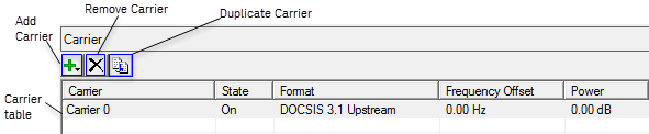
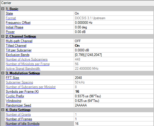
Double-click or use the drop-down menu to control the operating state of the carrier.
The format of the carrier.
Range: Depends on instrument and waveform settings
Set the frequency offset for the carrier relative to the signal generator’s frequency setting. Note: according to signal's bandwidth, the max frequency offset of each format will less than 80MHz
The valid range will be different for every format with various oversampling ratio.
Range: 0 to 359 degrees
Set the initial phase of the carrier.
Range: -50 to 0 dB
Sets the power level in dB for the selected carrier in a multiple carrier configuration, relative to the power settings defined for the other carriers in the configuration.
Click
 in the right side of the cell to open the
 ![]() Multi-path Channel configuration window. The default is OFF and you can change Multi-path Parameter” to User Defined and set the paths in the table.
Multi-path Channel configuration window. The default is OFF and you can change Multi-path Parameter” to User Defined and set the paths in the table.
User Defined provides a more flexible way configuring each path's attenuation ρ, relative delay τ and phase shift from scattering θ.
You can edit the parameters values in the table directly. Alternatively, click on the Open button, and select a fading file (*.fading) previously configured.
When you finished editing the user defined parameter configuration, click on Save button to make a copy.
Display the attenuation of the i'th path.
If Attenuation of all paths are zero, there will be an error when you click OK to close this dialog.
Displays the ralative delay of the i'th path.
When this valus is too large, there will be an out-of-memory exception that ask you to decrease it.
Displays the phase shift of the i'th path.
This is a radian value, so 2*pi has the same meaning with 0.
Choice: On | Off
Default: Off
Coupling: When Tilted Channel is off (default), the Tilt per Subcarrier will not be activated.
Get/Set whether tilted channel is enabled.
See also, Generating a Tilt Spectrum for DOCSIS 4.0.
Range: -1dB to 1dB
Resolution of tilt: 0.0001dB
Default: 0 dB
Coupling: When Tilted Channel is off (default), the Tilt per Subcarrier will not be activated.
Get/Set the tilt amplitude per subcarrier in dB.
See also, Generating a Tilt Spectrum for DOCSIS 4.0.
Gets or sets the exclusion bands. The bands are separated by "," and surrounded by "[" and "]". For example, [0,799],[1428,2047] means 2 bands, one is from subcarrier 0 to subcarrier 799, the other is from subcarrier 1428 to subcarrier 2047.The number of continuous subcarriers which are not excluded should contain integer minislots.
For FFT Size is 2048, some exclusion bands for typical bandwidths are:
24MHz: [0,799],[1248,2047]
48MHz: [0,553],[1498,2047]
96MHz: [0,73],[1970,2047]
For FFT Size is 4096, some exclusion bands for typical bandwidths are:
24MHz: [0,1573],[2518,4095]
48MHz: [0,1107],[2980,4095]
96MHz: [0,147],[3940,4095]
Gets the number of active subcarriers of DOCSIS 4.0 Upstream carrier. Active means not in the exclusion bands.
This is always read-only and determined by Exclusion Bands.
Gets the maximum number of minislots per frame of DOCSIS 4.0 Upstream carrier. This is always read-only and determined by exclusion bands and FFT size.
Gets the active signal bandwidth of DOCSIS 4.0 Upstream carrier. This parameter is always read-only and determined by Exclusion Bands.
Choices: 2048 | 4096
Default: 2048
Double-click or use the drop-down menu to select the FFT size for the OFDM signal.
For multi-carrier case, this parameter is read-only and determined by the first carrier.
Choices: 50kHz | 25kHz
Default: 50kHz
Gets the subcarrier spacing for the OFDM. This parameter is always read-only and determined by FFT Size.
Choices: 8 | 16
Default: 8
Gets the number of subcarriers per minislot. This parameter is always read-only and determined by FFT Size.
Range: 6 to 36
Default: 16
Gets or sets the number of symbol periods per frame.
Choices: 0.9375 us (96*Tsu) | 1.25 us (128*Tsu) | 1.5625 us (160*Tsu) | 1.875 us (192*Tsu) | 2.1875 us (224*Tsu) | 2.5 us (256*Tsu) | 2.8125 us (288*Tsu) | 3.125 us (320*Tsu) | 3.75 us (384*Tsu) | 5.0 us (512*Tsu) | 6.25 us (640*Tsu)
Default: 0.9375 us (96*Tsd)
Double-click or use the drop-down menu to select the cyclic prefix time (points) for the OFDM signal.
For multi-carrier case, this parameter is read-only and determined by the first carrier.
Choices: 0 us (0*Tsu) | 0.3125 us (32*Tsu) | 0.625 us (64*Tsu) | 0.9375 us (96*Tsu) | 1.25 us (128*Tsu) | 1.5625 us (160*Tsu) | 1.875 us (192*Tsu) | 2.1875 us (224*Tsu)
Default: 0.625 us (64*Tsd)
Double-click or use the drop-down menu to select the windowing roll-off time (points) for the OFDM signal.
Gets or sets the randomization seed in the format of Hex. This is a string composed of "0" to "9" and "A" to "F".
Gets the number of grants. This parameter is always read-only and determined by the added grants.
Range: 1 to 20
Default: 1
Gets or sets the number of frames to be generated.
Range: 1 to 36
Default: 16
Gets or sets the number of idle symbols without data modulated. These symbols will be added behind the generated frames.